I have been using a clock with built-in temperature and humidity sensors for monitoring ambient conditions in my room. For years it has run, I realized I was missing something: historical trend data, represented by a line chart. A quick solution for this would be a commercial internet-connected temperature monitoring devices, e.g. SensorPush and many others.
But, why would I buy something that I can build myself?
That thought had been marinating for months, only to be pursued recently in November 2021 when I learned about Raspberry Pi (RasPi) Pico, an inexpensive $4 microcontroller, powered by an RP2040 processor. I have known about Arduino boards for more than a decade, but I am not good enough in C++ to be able to use them. With RasPi Pico, we can program it using MicroPython or MicroPython-derivative maintained by Adafruit, CircuitPython. Installing either firmware is simple: drag the UF2 installer file into the Pi Pico (if it appears as a storage device), and it will reboot itself into the newly installed firmware shortly afterwards.
Without any firmware, RasPi Pico appears as storage device labeled as RPI-RP2. Note that after flashing with MicroPython UF2 firmware, the board will no longer appear on This PC. If flashed with CircuitPython UF2 firmware, it appears as a storage device labeled CIRCUITPY with read/write operation enabled. This reason alone makes it appealing to use CircuitPython to program a RasPi Pico since we can access the storage through Windows Explorer (or whatever file manager).
My first project, an internet-connected temperature monitor, uses an AHT20 sensor (Adafruit cat. # 4566) and AirLift ESP32 WiFi co-processor breakout board (Adafruit cat. # 4201). With CircuitPython, getting them running was relatively painless, thanks to library bundles (v7.x, zip archive of 3.5 MB) provided by CircuitPython. Otherwise, I would have to look for libraries separately when running on MicroPython. I write python codes using Thonny IDE and couldn’t outgrow it even after I figured out how to use VS Code with Pico-Go extension by Chris Wood.
Wiring Boards
First problem: I purchased the wrong wire. Instead of purchasing a 22AWG solid core spool set (Adafruit cat. # 1311), I got a 22AWG stranded core spool set from Plusivo (Amazon cat. # B07T4SYVYG). I realized that after trying to insert the stripped wire (with great difficulty!) into a breadboard. Thankfully, I purchased a 22AWG jumper wire bundle (Adafruit cat. # 3314), so I was able to get started wiring the components together. For my modest IoT temperature monitor, I connected AHT20 and AirLift ESP32 to the RasPi Pico running on CircuitPython.
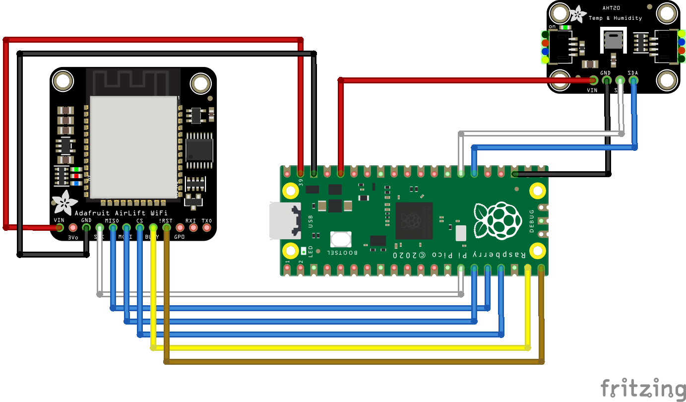
And here is the pin connection table, each row indicates connection.
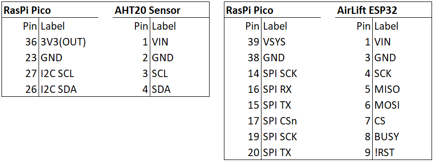
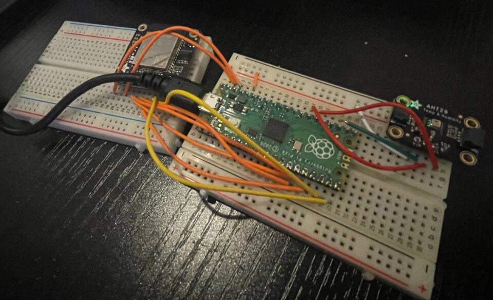
The sketch looks fairly decent. The actual wiring looks whatever the opposite of feng shui.
Testing On-Board LED
Somewhat important to verify the RasPi Pico is actually working.
The onboard LED is located at pin 25.
If we are using MicroPython, the LED can be configured with Pin(25, Pin.OUT).
Whereas with CircuitPython, the onboard LED address is already abstracted as board.LED.
This just illustrates a minor difference between both firmwares.
Dramatic differences would be more obvious when using breakout boards, where CircuitPython’s extensive driver libraries makes it extremely useful and quick to get them running.
# Using MicroPython ----------------------------------------
from machine import Pin, Timer
led = Pin(25, Pin.OUT)
timer = Timer()

def blink(timer):
    led.toggle()

timer.init(freq=2.5, mode=Timer.PERIODIC, callback=blink)

# Using CircuitPython --------------------------------------
import time
import board
import digitalio

led = digitalio.DigitalInOut(board.LED)
led.direction = digitalio.Direction.OUTPUT

while True:
    led.value = True
    time.sleep(0.1)
    led.value = False
    time.sleep(0.5)
The onboard LED only blinks green (not an RGB), otherwise it would be really cool to use it for indicating different statuses (e.g. “error” blinks “red”,). Notwithstanding that, it serves its purpose well. I set it to blink upon a successful booting, after establishing a WiFi connection, and after pushing data to an MQTT broker. I even wrote a function to abstract out the blinking instead of having to write a loop every few blocks.
# file: led_repeater.py
"""CircuitPython LED repeater
A small function to abstract internal LED blinking
"""
import time
import board
import digitalio

# Configure on-board LED
led = digitalio.DigitalInOut(board.LED)
led.direction = digitalio.Direction.OUTPUT

# Importable function
def internal_blinker(repeat=1, sleep=0.2):
    # Create a list to hold our "repeater" value
    n = [1]
    _lst = n * repeat

    # Loop the blinker
    for i in _lst:
        led.value = True
        time.sleep(sleep)
        led.value = False
        time.sleep(sleep)

# If run directly, blink 10 times
if __name__ == "__main__":
    internal_blinker(repeat=10)
To use internal_blinker() function, simply import and call it.
# Import
from led_repeater import internal_blinker

# Run
internal_blinker(repeat=3)
Testing AHT20 Sensor
Using adafruit_ahtx0.mpy module (CircuitPython), it is quite trivial to get readings from the sensor.
AHT20 uses I2C (I-squared-C, stands for inter-integrated circuit) for communication.
The minimum working code is shown below.
import time
import busio
import board
import digitalio
import adafruit_ahtx0

# Configure AHT20 temp and humidity sensor
i2c = busio.I2C(scl=board.GP21, sda=board.GP20)
sensor = adafruit_ahtx0.AHTx0(i2c)

# Print to terminal
while True:
    print("\n")
    print("Temperature: %0.1f C" % sensor.temperature)
    print("Humidity: %0.1f %%" % sensor.relative_humidity)

    time.sleep(1)
Compared with the DHT22 sensor, AHT20 does not have “lag sensor read time” (I do not know the exact terminology).
With DHT22, new data is spit for every 2 seconds due to its 0.5 Hz sampling rate, requiring a “wait” time to get fresh data.
This is straightforward to deal with by having time.sleep(2) (sleep for 2 seconds) when using DHT22.
Regardless, reading data infrequently (i.e. every few seconds instead of multiple times per second) is a good way to not overheat (?) the sensor chip.
Testing AirLift ESP32
As I understand it, ESP32 can be controlled by using AT commands.
The adafruit_esp32spi module (CircuitPython) simplifies the process and provides an excellent abstraction for connecting to an access point (AP).
It includes a WiFi manager class adafruit_esp32spi_wifimanager that takes care of connecting, resetting, and reconnecting to an AP.
This is especially useful, instead of using the esp.connect_AP() function that is more verbose.
Note that this ESP32 board can only connect to 2.4 GHz AP.
import time
import busio
import board
import digitalio
from adafruit_esp32spi import adafruit_esp32spi
from adafruit_esp32spi import adafruit_esp32spi_wifimanager
import adafruit_esp32spi.adafruit_esp32spi_socket as socket
import adafruit_requests as requests

# Set socket (for requests library) to use esp -------------
requests.set_socket(socket, esp)

# Read WiFi secrets ----------------------------------------
try:
    from secrets import secrets
except ImportError:
    print("Secrets not found, aborting...")
    raise

# Assigning pins -------------------------------------------
esp32_cs = digitalio.DigitalInOut(board.GP13)
esp32_ready = digitalio.DigitalInOut(board.GP14)
esp32_reset = digitalio.DigitalInOut(board.GP15)
spi = busio.SPI(board.GP10, board.GP11, board.GP12)
esp = adafruit_esp32spi.ESP_SPIcontrol(spi, esp32_cs, esp32_ready, esp32_reset)

# Check ESP32 status ---------------------------------------
if esp.status == adafruit_esp32spi.WL_IDLE_STATUS:
    print("ESP32 found and in idle mode")
print("Firmware version: ", bytearray(esp.firmware_version).decode())

# Scan available WiFi APs ----------------------------------
for ap in esp.scan_networks():
    print("\t%s\t\tRSSI: %d" % (str(ap['ssid'], 'utf-8'), ap['rssi']))

# Using esp.connect_AP() -----------------------------------
print("Connecting to an AP...")
while not esp.is_connected:
    try:
        esp.connect_AP(secrets["ssid"], secrets["password"])
    except RuntimeError as e:
        print("Failed to connect to an AP, retrying: ", e)
        continue
print("Connected to", str(esp.ssid, "utf-8"), "\tRSSI:", esp.rssi)
print("Local IP address:", esp.pretty_ip(esp.ip_address))

# Using wifimanager ----------------------------------------
wifi = adafruit_esp32spi_wifimanager.ESPSPI_WiFiManager(esp, secrets)
wifi.connect()
print("WiFi Connected!")
Sending Sensor Data
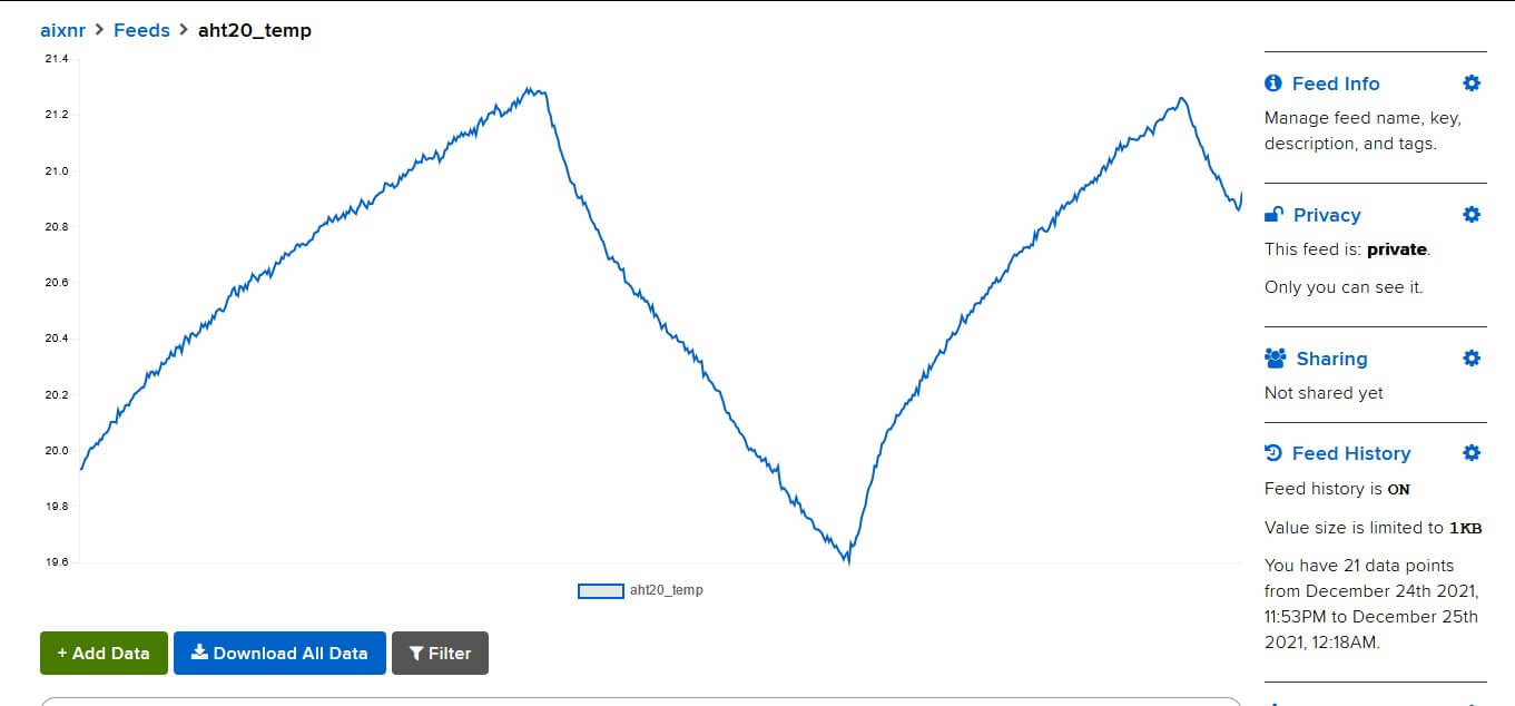
For my initial test, I used Adafruit IO cloud service.
My impression is that it is an MQTT broker and a data dashboard.
For beginners and for testing purposes, it works great!
There is also another commercial MQTT broker, HiveMQ, with a decent free-tier offering (I have not tried it yet).
In a separate article, I will describe my experience running a self-hosted MQTT broker using mosquitto package on a linux OS.
To summarize the next article, I have a Flask app with paho-mqtt (on the machine that is hosting the MQTT broker) to subscribe messages from a set of defined topics.
For collecting data, I use prometheus_client to expose the collected message payloads, which are then scraped by a Prometheus server.
Prometheus is my go-to time series database only because I have a Grafana dashboard server running.
Adafruit has tutorials on working with Adafruit IO service and this overview article is the best place to get started. I first started by following their tutorial on connecting RasPi Pico with WiFi with ESP32. Bear in mind that Adafruit IO is a freemium service, so free-tier users have to be mindful of its limitations.
I am not (yet?) an expert on MQTT, and getting used to it was not quick. This includes learning the terminology (it is a “broker”, not a “server”), understanding the “callbacks” and how they work (see this explanation by Steve), etc. But hey, it works!
Closing Words
I do not have a git repository (yet) for organizing scripts.
However, I uploaded my code.py script (link to GitHub Gist) that reads sensor data from a AHT20 and publishes to Adafruit IO through ESP32.
This code requires secrets.py that holds a dictionary of credentials.
secrets = {
    "ssid": "WiFI AP ssid",
    "password": "WiFI AP password",
    "timezone": "America/New_York",
    "aio_username": "adafruit_io_username",
    "aio_key": "adafruit_io_key"
}
Thinking about it, it is funny that I managed to squeeze a bit of time to learn something new, soldering and assembling the boards, writing and testing codes, and writing this piece over a short Christmas weekend of 2021. That is a fairly respectable speed, actually!